You are here:

100G OTN Digital Core
The OTL4 core (Optical Transport Lane of OTU4) implements the OTL4 layer function of ITU-T G.709. The OTL4 interface can be used in OTU4 or OTUCn application.
At the time of this page is written, there are 3 types of OTL4 interface.
4 – there are 4 transport lanes to carry the OTU4 data
10 – there are 10 transport lanes to carry the OTU4 data
2 – there are 2 transport lanes to carry the OTU4 data ** newly added for 50G serdes/optics **
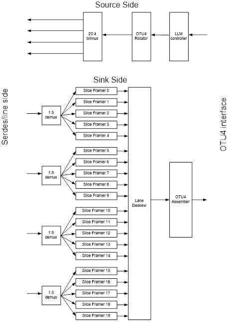
The architecture of the OTL4 for both types is fundamentally the same except at the serdes/optic facing side (the “line” side). The following block diagram outlines the internal architecture of the OTL4.4.
For OTL4.10, in the source side, twenty 2:1 bitmuxes are used after the OTU4 rotator. Likewise, in the sink side, ten 1:2 demuxes are used before 20 slice framers.
For OTL4.2, in the source side, two 10:1 bitmuxes are used after the OTU4 rotator. Likewise, in the sink side, two 1:10 demuxes are used before 20 slice framers.
OTL4 uses 20 logical lanes to carry an OTU4 frame. Each logical lane is marked with LLM. Since each logical lane is marked or tagged with the LLM, random bitmux bundling of logical lanes into physical lanes is allowed. E.g. for OTL4.4, user can bundle any combination of 5 logical lanes into 1 physical lane. Each LLM marked logical lane can be recovered and identified in the sink side. Thus OTL4 allows random connections of the external serdes links between the source side and the sink side. This eases PCB routing and multiple fiber connections when using OTL4 interface.
查看 100G OTN Digital Core 详细介绍:
- 查看 100G OTN Digital Core 完整数据手册
- 联系 100G OTN Digital Core 供应商
Block Diagram of the 100G OTN Digital Core


